Welcome to visit the website of HJ Polymer China Co., Ltd. ---Semi-conductive Compound Industry Solutions


 中文简体
 Français
 عربى


Welcome to visit the website of HJ Polymer China Co., Ltd. ---Semi-conductive Compound Industry Solutions

Content
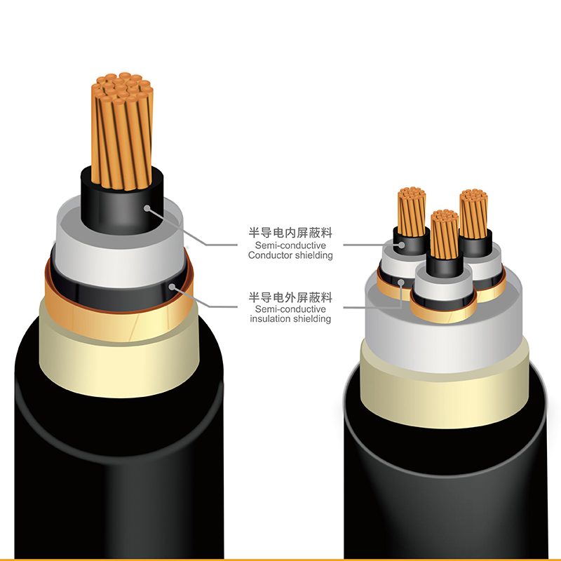
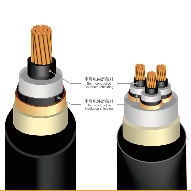
Strip back a medium-voltage cable and you will find a thin black layer that most people never think about. That is the conductor shield, the extruded semiconductive compound sitting between the stranded copper or aluminium and the insulation. It is often well under a millimetre thick, yet it carries a heavy job: smoothing the electric field around the conductor strands, filling the crevices between wires, and bonding tightly enough to the insulation that no air gap survives at the interface.
We have been compounding these materials at our Jiangyin plant since 2002, and one lesson keeps repeating itself. Cable problems blamed on insulation are very often rooted in the conductor shield. The reassuring part is that the properties which decide whether a shield performs are well understood, measurable, and controllable, provided the compound is designed and processed with the right discipline.
Think of the shield as a field-shaping layer. A conductor surface is not a perfect cylinder; it is a bundle of strands with crevices between them. Without a semiconductive layer filling those crevices, electric stress concentrates at the tips of individual strands and inside air pockets, and partial discharge begins at stresses the insulation alone could easily tolerate. The shield converts that rough geometry into a smooth equipotential surface.
Because the layer sits electrically in series between conductor and insulation, it also has to stay conductive in a predictable way. If its resistivity drifts with temperature, ageing or moisture, the field distribution across the cable changes, losses creep upward, and the design margin quietly erodes. That is why compound selection is a performance decision, not a procurement formality.
Volume resistivity is the headline number, and it is almost always quoted at room temperature. Most MV specifications call for values below roughly 100 Ω·cm at 23 °C, with a separate, higher ceiling at the maximum conductor temperature, typically 90 °C. A compound that passes comfortably at 23 °C but climbs steeply at 90 °C is not the same material in service. The conductive carbon black network, the viscosity of the polymer matrix and the final crosslink density all influence that curve, which is why we test resistivity at both temperatures on every production batch.
Protrusions, waviness and gels at the shield surface create local field enhancements right where the insulation sees them. Smoothness limits are usually written in tens of micrometres for standard MV constructions and tighten considerably as stress rises. Smoothness is not simply a resin property. It is the combined outcome of filtration, dispersion, die and crosshead design, and the stability of the melt being pumped.
A single fibre, a metal speck or an unmelted pellet can create a defect that survives every electrical test at the factory and then grows in service. Compound cleanliness is the hardest property to verify on finished cable, so it has to be built in at the compounding stage through incoming raw material screening, closed conveying systems and screen packs chosen for the grade. Specifications often express this as an allowed number of oversized contaminants per kilogram; the practical target is zero.
Conductive carbon black turns an insulating polyolefin into a semiconductive one. Poor dispersion causes two problems at once: an uneven conductive network that shows up as erratic resistivity and local heating, plus agglomerates that behave like protrusions at the interface. Well-dispersed black gives tight batch-to-batch resistivity and a consistent surface finish. It also stabilises cure behaviour, since poorly wetted black changes how the peroxide reacts.
MV conductor shields are almost always peroxide crosslinkable and are cured in the same continuous or vertical tube as the insulation. The cure package therefore has to be compatible with the insulation beside it. Scorch time at extrusion temperature must leave enough room to survive a stop-start run without gel, while cure rate must match line speed and tube length so all three layers reach the right crosslink density together. A mismatch shows up as adhesion loss, interface waviness or an undercured shield that fails hot-set checks.
Tensile strength above 12 MPa and elongation at break above 200% are common acceptance values for crosslinked MV conductor shields, with hot-set and permanent deformation limits confirming the cure state. Adhesion is a deliberate design choice. Conductor shields are normally bonded firmly to both conductor and insulation so that no void can form; insulation shields may be bonded or strippable, and strippable grades use quite different chemistry to give a clean peel without tearing. Standards work in this area continues to shape how those trade-offs are specified, and the differences between bonded and strippable constructions are worth understanding before a drawing is frozen.
Bonded, strippable and standards-driven MV conductor shield design
Cables spend decades at 90 °C with copper pressed against the shield. Copper-catalysed oxidation is a real degradation path, so grades intended for copper conductors carry a tailored antioxidant package validated by air-oven ageing. Volatiles matter too: residues left in the compound can migrate into the insulation or condense in voids, so degassing and controlled storage are part of performance, not housekeeping.
The table below is a working summary we use when discussing a new MV project. Exact limits always follow the cable standard and the customer's own specification.
| Property | What it controls | Typical expectation |
|---|---|---|
| Volume resistivity, 23 °C | Field distribution, losses | Below 100 Ω·cm |
| Volume resistivity, 90 °C | Margin at operating temperature | Separate, higher ceiling |
| Surface smoothness | Local field enhancement | Tens of micrometres |
| Contamination level | Defect initiation, long-term life | Effectively zero oversized particles |
| Carbon black dispersion | Resistivity consistency, finish | Microscopically uniform |
| Scorch time at extrusion temperature | Run stability, gel risk | Safe stop-start window |
| Tensile strength and elongation | Mechanical integrity | Above 12 MPa and 200% |
| Adhesion to conductor | Void-free interface | Firmly bonded |
Two cables can share a drawing number and still need different compounds, because line speed, conductor type and the extrusion head all push the choice. It is common for us to supply the same project with more than one grade for exactly this reason.
 HJ0301 General-Purpose MV Conductor Shielding CompoundA general-purpose crosslinkable semiconductive shield for conventional triple-extrusion MV lines, balancing scorch safety and cure speed for conductor shield projects.View Product →
HJ0301 is where most MV conductor shield projects start: a general-purpose crosslinkable semiconductive conductor shielding compound for MV power cables, with the balance of scorch safety and cure speed that suits a conventional triple-extrusion line.
 HJ0304 High-Speed MV Conductor Shielding CompoundFor fast, large-section MV lines, this compound supports up to 10 m/min and 500 mm² while targeting scorch resistance and smooth shield surfaces.View Product →
When the line runs fast, cure kinetics rather than resistivity become the limiting factor. HJ0304 was developed for fast MV production lines, where the shield has to reach full crosslink density in a shorter tube residence time without sacrificing surface quality.
 HJ0305 Copper-Oxidation-Resistant MV Conductor ShieldA bonded semiconductive shield for copper conductors up to 36 kV, using special antioxidants to limit copper oxide formation and support long-term thermal ageing stability.View Product →
For copper conductors, HJ0305 adds the copper-contact ageing protection described earlier, keeping resistivity and mechanical properties stable through long-term thermal ageing.
If you are still mapping out which construction you need, the overview of MV conductor shield compounds shows how conductor and insulation shields are grouped by application.
Even a well-designed compound can be undone on the line. A short checklist we share with cable makers:
Compound qualification is a slow process by nature. Our own history traces it: participation in drafting the JB/T 10738-2007 industry standard, a Jiangsu provincial engineering research centre for cable shielding composites established in 2013, UL recognition of our products in 2015, and work on the State Grid 220 kV high-voltage shielding compound standard in 2018. Across thirteen dedicated production lines and roughly 62,000 tonnes of annual capacity, the same logic applies to MV conductor shields: define the property window, control the process that delivers it, and measure both.
If you are comparing compounds for a new MV construction, bring us the cable design, the line profile and the standard you are working to. Matching those three is usually the fastest route to a shield that behaves predictably in the tube and in the ground.